- 您现在的位置:买卖IC网 > Sheet目录1905 > ATMEGA8HVA-4CKU (Atmel)MCU AVR 8K FLASH 4MHZ 36-LGA
136
8024A–AVR–04/08
ATmega8HVA/16HVA
24.2
FET Driver
24.2.1
Features
Charge-pump for generating suitable gate drive for N-Channel FET switch on high side
Deep Under-voltage Recovery mode that allows normal operation while charging a Deeply Over-
discharged battery from 0-volt
24.2.2
Overview
The ATmega8HVA/16HVA includes a FET Driver. The FET Driver is designed for driving N-
channel FETs used as high side switch in 1- or 2-Cell Li-Ion battery pack. A block diagram of the
FET driver is shown in Figure 24-2 on page 136.
When charging deeply over-discharged cells, the FET Driver will be operated in Deep Under-
Voltage Recovery (DUVR) mode. In DUVR mode the FET Driver regulates the voltage at the
VFET pin to typically 2.0 Volts in 1-Cell applications and typically 4.0 Volts in 2-Cell applications.
This is done by operating the Charge FET at a point where the drain-source voltage is equal to
the voltage difference between the cell voltage and the required VFET operating voltage. As the
cell voltage increases, the drain-source voltage of the Charge FET will decrease until the
Charge FET is completely on. See Table 29-5 on page 170 for details.
In normal operation (DUVRD = 1), the Charge FET/Discharge FET is switched on by pumping
OC/OD sufficiently above the VFET supply voltage. To turn off the Charge FET/Discharge FET,
OC/OD is pulled quickly low. See Figure 24-3 on page 137 and Table 29-5 on page 170 for
details.
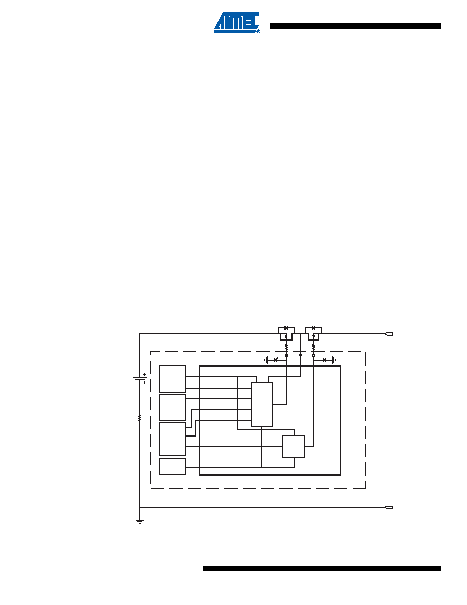
Figure 24-2. FET Driver block diagram.
Discharge FET
Charge FET
OD
OC
BATT+
BATT-
VFET
NFET DRIVER
DUVRD
D-FET
Charge
Pump
CHARGE_EN
DISCHARGE_EN
FET
CONTROL
C-FET
Charge
Pump
DUALC_MODE
LDO
_VREG
DVDD
VREF
BANDGAP
REF.
CLK
CLK_OSC
1k
14V clamp
发布紧急采购,3分钟左右您将得到回复。
相关PDF资料
ATSAM3N4AA-AU
MCU FLASH 48-QFP
ATSAM3SD8CA-CU
IC MCU 2X256KB CORTEX-M3 100-QFN
ATSAM3U1EB-CU
IC MCU 64KB CORTEX-M3 144-TFBGA
ATSAM3X8EA-CU
IC MCU 2X256KB CORTEX-M3 144-BGA
ATTINY12V-1SUR
IC AVR MCU 1K FLASH 4MHZ 8-SOIC
ATTINY13-20SQR
IC MCU AVR 1KB FLASH 20MHZ 8SOIC
ATTINY13A-MMUR
MCU AVR 1KB FLASH 20MHZ 10DFN
ATTINY13V-10SUR
MCU AVR 1KB FLASH 10MHZ 8SOIC
相关代理商/技术参数
ATMEGA8HVA-4CKUR
功能描述:8位微控制器 -MCU AVR 8KB FLSH 512B EE 1KB SRAM - 4 MHZ RoHS:否 制造商:Silicon Labs 核心:8051 处理器系列:C8051F39x 数据总线宽度:8 bit 最大时钟频率:50 MHz 程序存储器大小:16 KB 数据 RAM 大小:1 KB 片上 ADC:Yes 工作电源电压:1.8 V to 3.6 V 工作温度范围:- 40 C to + 105 C 封装 / 箱体:QFN-20 安装风格:SMD/SMT
ATMEGA8HVA-4TU
功能描述:8位微控制器 -MCU AVR 8KB, 512B EE 4MHz 1KB SRAM 1.8-9V RoHS:否 制造商:Silicon Labs 核心:8051 处理器系列:C8051F39x 数据总线宽度:8 bit 最大时钟频率:50 MHz 程序存储器大小:16 KB 数据 RAM 大小:1 KB 片上 ADC:Yes 工作电源电压:1.8 V to 3.6 V 工作温度范围:- 40 C to + 105 C 封装 / 箱体:QFN-20 安装风格:SMD/SMT
ATMEGA8HVA-4TUR
功能描述:8位微控制器 -MCU AVR 8KB FLSH 512B EE 1KB SRAM - 4 MHZ RoHS:否 制造商:Silicon Labs 核心:8051 处理器系列:C8051F39x 数据总线宽度:8 bit 最大时钟频率:50 MHz 程序存储器大小:16 KB 数据 RAM 大小:1 KB 片上 ADC:Yes 工作电源电压:1.8 V to 3.6 V 工作温度范围:- 40 C to + 105 C 封装 / 箱体:QFN-20 安装风格:SMD/SMT
ATMEGA8HVD-4MX
功能描述:8位微控制器 -MCU AVR 8KB, 512B EE 4MHz 1KB SRAM 2.1-8V
RoHS:否 制造商:Silicon Labs 核心:8051 处理器系列:C8051F39x 数据总线宽度:8 bit 最大时钟频率:50 MHz 程序存储器大小:16 KB 数据 RAM 大小:1 KB 片上 ADC:Yes 工作电源电压:1.8 V to 3.6 V 工作温度范围:- 40 C to + 105 C 封装 / 箱体:QFN-20 安装风格:SMD/SMT
ATMEGA8L-8AC
功能描述:8位微控制器 -MCU AVR 8K FLASH 512B EE 1K SRAM ADC 3V RoHS:否 制造商:Silicon Labs 核心:8051 处理器系列:C8051F39x 数据总线宽度:8 bit 最大时钟频率:50 MHz 程序存储器大小:16 KB 数据 RAM 大小:1 KB 片上 ADC:Yes 工作电源电压:1.8 V to 3.6 V 工作温度范围:- 40 C to + 105 C 封装 / 箱体:QFN-20 安装风格:SMD/SMT
ATMEGA8L8AI
制造商:Atmel Corporation 功能描述:
ATMEGA8L-8AI
功能描述:8位微控制器 -MCU AVR 8K FLASH 512B EE 1K SRAM ADC 3V RoHS:否 制造商:Silicon Labs 核心:8051 处理器系列:C8051F39x 数据总线宽度:8 bit 最大时钟频率:50 MHz 程序存储器大小:16 KB 数据 RAM 大小:1 KB 片上 ADC:Yes 工作电源电压:1.8 V to 3.6 V 工作温度范围:- 40 C to + 105 C 封装 / 箱体:QFN-20 安装风格:SMD/SMT
ATMEGA8L-8AJ
功能描述:IC MCU AVR 8K 5V 8MHZ 32-TQFP RoHS:是 类别:集成电路 (IC) >> 嵌入式 - 微控制器, 系列:AVR® ATmega 标准包装:9 系列:87C 核心处理器:8051 芯体尺寸:8-位 速度:40/20MHz 连通性:UART/USART 外围设备:POR,WDT 输入/输出数:32 程序存储器容量:32KB(32K x 8) 程序存储器类型:OTP EEPROM 大小:- RAM 容量:256 x 8 电压 - 电源 (Vcc/Vdd):4.5 V ~ 5.5 V 数据转换器:- 振荡器型:内部 工作温度:0°C ~ 70°C 封装/外壳:40-DIP(0.600",15.24mm) 包装:管件